


A: Here is the wifi instrcution link: https://drive.google.com/file/d/1TXX5AyM4NvtoGDnUFIblrxbJtIazHb5Z/view
 EN
EN
EN
EN


Fault Status: The buzzer emits a continuous beep, and the red light is on.
Bus soft start failure.
After system power-up, check if the bus capacitor voltage is less than 300V: If the bus voltage is low, it indicates a failure in the soft start process.
Check if the battery voltage is normal: Verify that the battery is within the correct voltage range and is functioning properly.
Check if the PV input voltage is normal: Ensure that the input voltage from the PV system is within the expected range.
If the battery or PV fails to soft start normally: Inspect whether the soft start circuit itself is malfunctioning.
Pro Model:
If the device powers on with only the PV connected and reports error code 09, it may not necessarily indicate a system crash. It could be due to low input voltage from the PV system or insufficient power being provided to the system. In this case, turn off the device, connect the battery or mains power, and then restart to see if the error is resolved.
Non-Pro Model:
A failure in the soft start process typically indicates a system crash. In this case, follow the error maintenance manual for troubleshooting or replace the power board if necessary.
For Pro Models:
If the battery is connected, but the system still shows error code 09, check the IGBT (Insulated Gate Bipolar Transistor). If it is damaged, it must be replaced.
Machine Status: The buzzer emits a continuous beep, and the red light is on.
Transformer temperature is too high.
The internal temperature of the inverter exceeds 100°C, and the transformer temperature exceeds 150°C.
The temperature may not necessarily exceed 100°C, as each machine has different calibration settings.
It may not be a problem with the transformer sensor; some machines do not sample the transformer's temperature.
Check if the fan speed is normal: Ensure the fan is operating correctly to assist with cooling.
Check if the transformer sensor is abnormal: Verify whether the temperature sensor is malfunctioning.
Consider load derating: Reduce the system load to alleviate temperature pressure.
Use the upper computer to check the inverter's displayed temperature: Monitor the temperature data through the system.
Physically touch the inverter casing: Check if the actual surface temperature of the inverter is high.
If the displayed temperature is high but the actual temperature is not: This may indicate an issue with the transformer’s NTC sensor.
Check if the dust filter is excessively clogged: Clean the filter to ensure airflow is not obstructed.
Check if the internal airflow paper is installed securely and completely: Ensure the cooling pathway is unobstructed for optimal airflow.
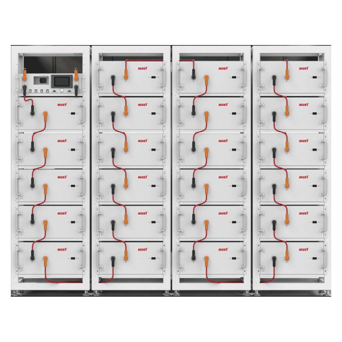
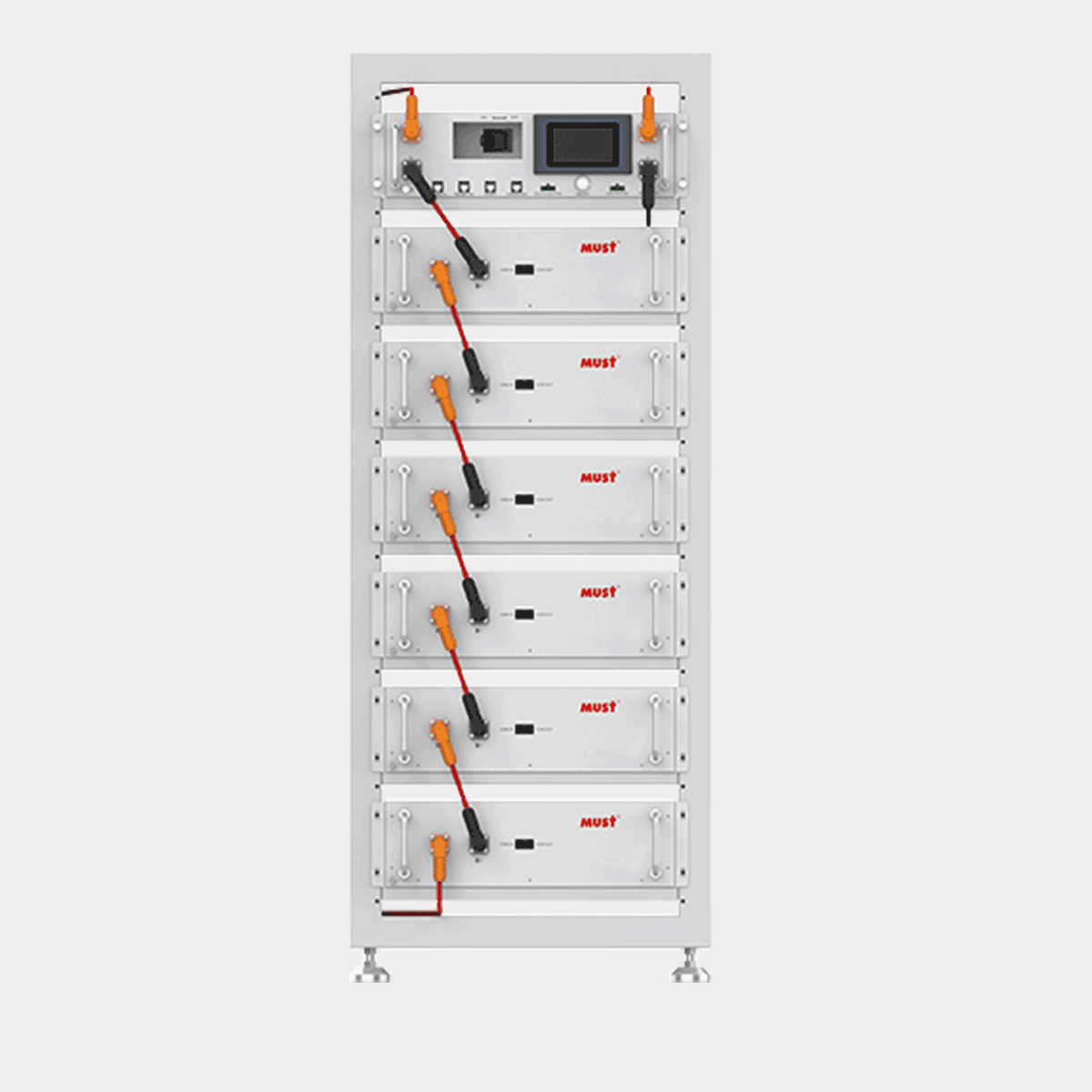
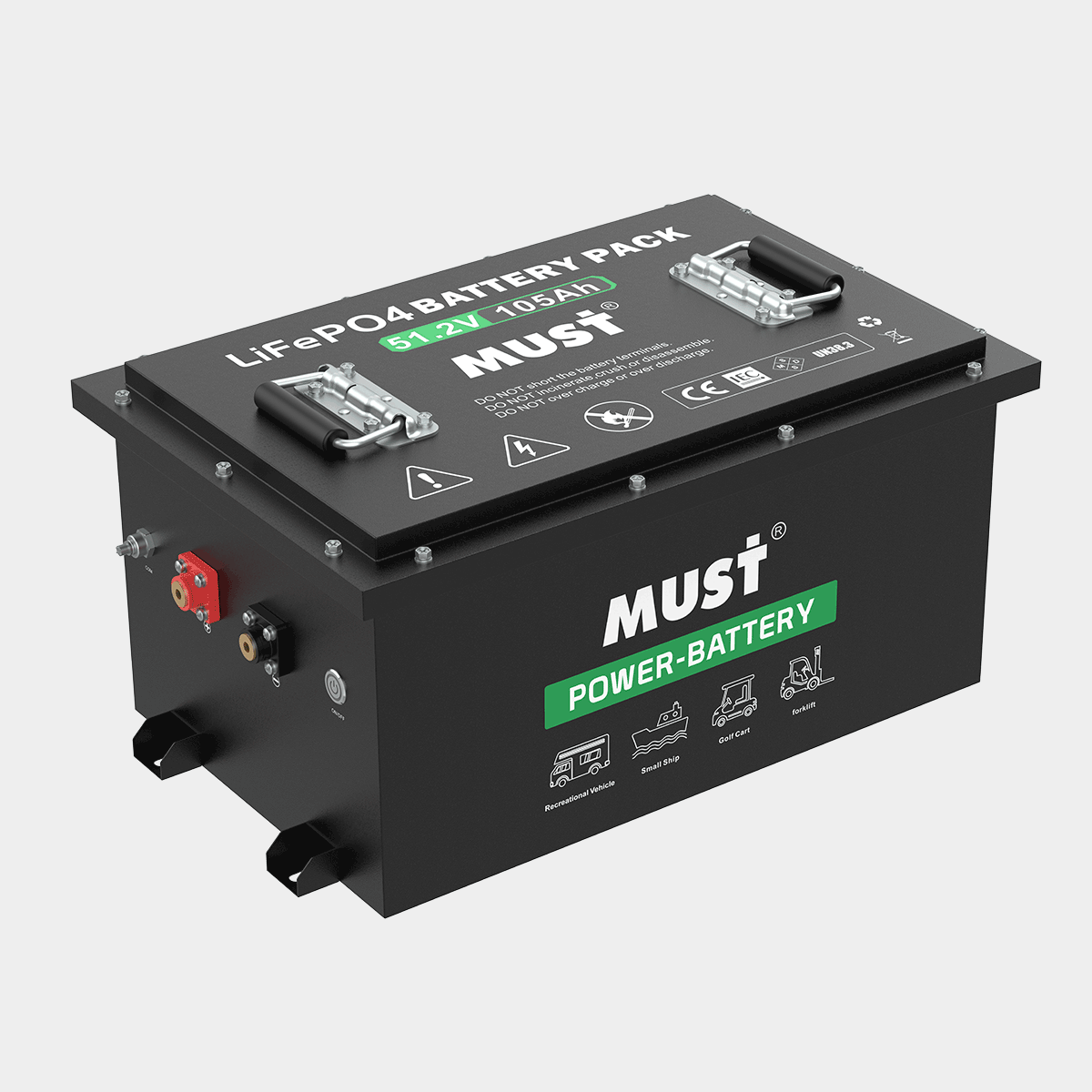
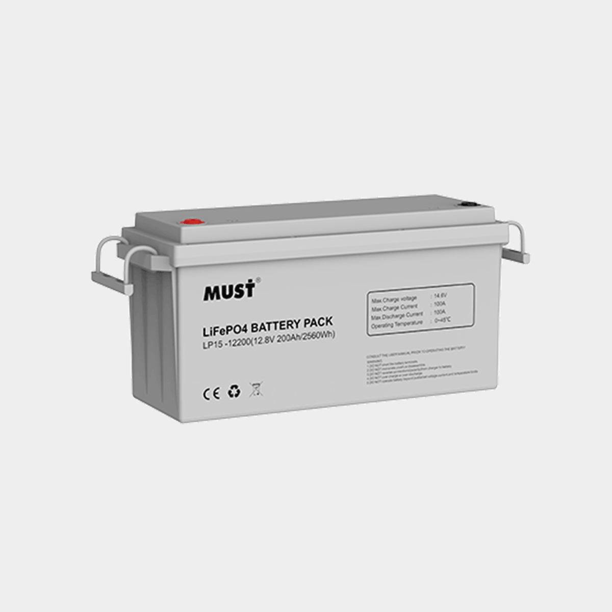
When the fuse in some batteries blows, these batteries will not participate in charging or discharging. As a result, the State of Charge (SOC) of these batteries will not change while other batteries are fully charged. The overall SOC of the parallel battery system will be an average of all individual battery SOCs, making it appear as though the batteries are not fully charged.
Inspection Method:
During charging and discharging, use the BMS monitor to read the SOC and current of each battery.
If there is a significant difference in SOC between some batteries and the others, and no current flow is detected in these batteries, it suggests that the fuse may have blown.
For batteries suspected of having a blown fuse, open the battery casing and check for continuity in the fuse.
If the cable connecting the inverter to the battery, or the parallel cables between batteries, is not securely connected, high contact resistance will occur. This results in the voltage received by the battery being lower than the charging voltage supplied by the inverter, preventing the battery from charging fully.
Inspection Method:
Use Solarman to monitor the voltage information sent by the battery to the inverter and compare it with the voltage detected by the inverter.
Under normal conditions, the voltage difference should be less than 0.5V.
Use the BMS monitor to read the voltage of each battery and check the connection of the parallel cables for any issues.
In Turbo V1.0.x firmware, the cell overcharge alarm threshold was modified to make it easier for the battery to calibrate SOC and charge to 100%. However, this change will only take effect if the "Reset to Default" option is selected in the BMS monitor after upgrading the firmware. If this step is skipped, the battery will continue operating under the original logic.
Inspection Method:
Use the BMS monitor to read the parameters of each battery.
Check if the cell overcharge alarm threshold is set to 3.6V. If not, click "Reset to Default" and then reread the parameters.

A: Here is the wifi instrcution link: https://drive.google.com/file/d/1TXX5AyM4NvtoGDnUFIblrxbJtIazHb5Z/view

You are warmly welcomed to join our global distributor network.

扫码关注
FOLLOW US


Keep in touch.Subscribe to our e-mails
MUST ENERGY © 2026 All rights reserved
by GrowthMan
China Headquarters
MUST ENERGY (GUANGDONG) TECHNOLOGY CO., LTD
sa@mustenergy.com
+86 755 83657660 (Europe)
+86 755 83651325 (Americas)


